
Circuit and working
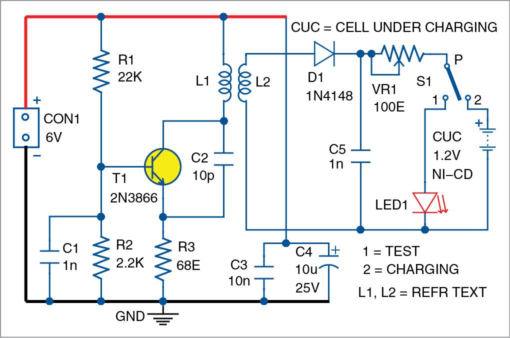
Circuit diagram of the contactless battery charger is shown in Fig. 1. It is built around npn transistor 2N3866 (T1), diode 1N4148 (D1), an LED (LED1) and a few other components.
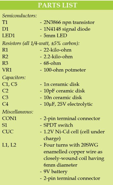
Transistor T1 forms the 100MHz RF medium-power oscillator. Inductors L1 and L2 are made with four turns of 20SWG enamelled copper wire as closely-wound coils having 6mm diameter. Coil L2 is kept near L1 (around 2mm apart). There is no electrical contact between L1 and L2, but RF (VHF) signals from L1 get induced to L2. Signals obtained from L2 are sufficient to drive LED1 or charge a 1.2V rechargeable cell (Nickel-Cadmium) after rectification and filtration.
Transistor T1 forms the 100MHz RF medium-power oscillator. Inductors L1 and L2 are made with four turns of 20SWG enamelled copper wire as closely-wound coils having 6mm diameter. Coil L2 is kept near L1 (around 2mm apart). There is no electrical contact between L1 and L2, but RF (VHF) signals from L1 get induced to L2. Signals obtained from L2 are sufficient to drive LED1 or charge a 1.2V rechargeable cell (Nickel-Cadmium) after rectification and filtration.
Construction and testing
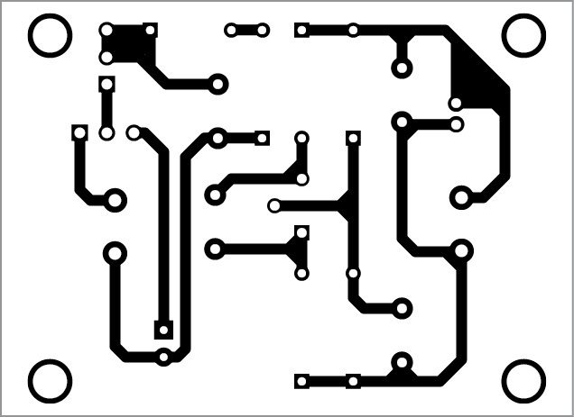
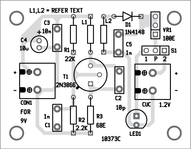
An actual-size, single-side PCB layout of the contactless battery charger is shown in Fig. 2 and its components layout in Fig. 3. After assembling the circuit on a PCB, enclose it in a suitable plastic box. Place L1 and L2 next to each other such that LED1 glows when switch S1 is at position 1. When S1 is at position 2, you can charge a 1.2V rechargeable cell.
The circuit works off 9-12V battery power supply.
The circuit works off 9-12V battery power supply.
Download PCB and Component Layout PDFs: Click here
Pradeep G. is B.Sc. (Physics) and a regular contributor to international magazines. He is also a small-business owner in south India
Fig. 1: Circuit diagram of the contactless battery charger
Fig. 2: Actual-size PCB layout of the contactless battery charger
Fig. 3: Components layout of the PCB
Note:-It is not Our own plan it is taken from other website
Fig. 2: Actual-size PCB layout of the contactless battery charger
Fig. 3: Components layout of the PCB
Note:-It is not Our own plan it is taken from other website

")
")

")
0 comments: