Now we are going to discuss about the Core Type Transformer & Shell Type Transformer
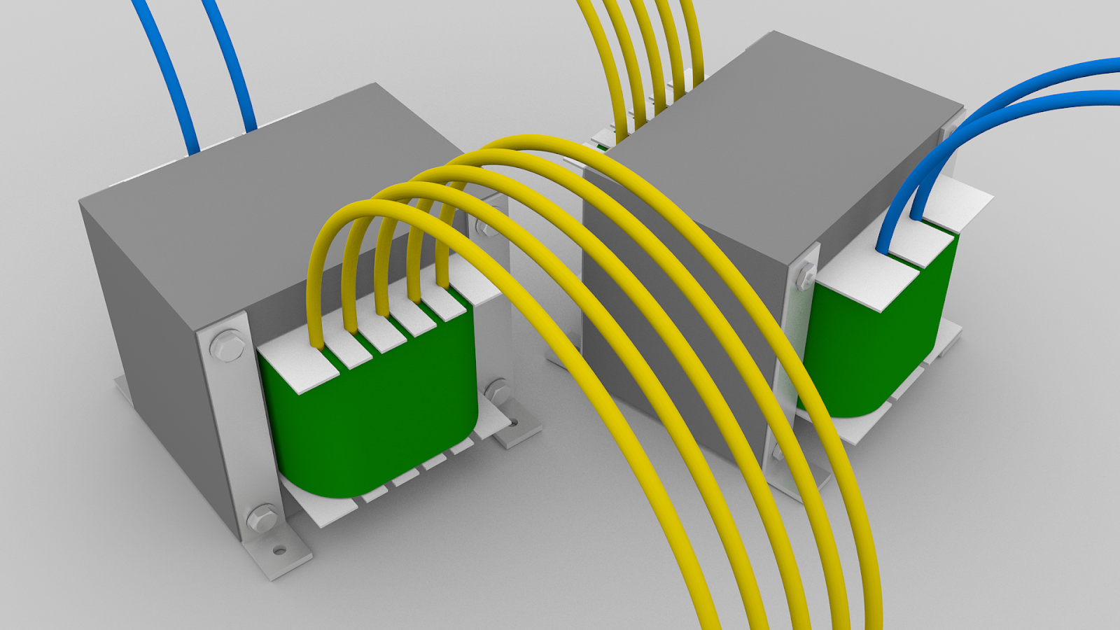
Core Type Transformer :
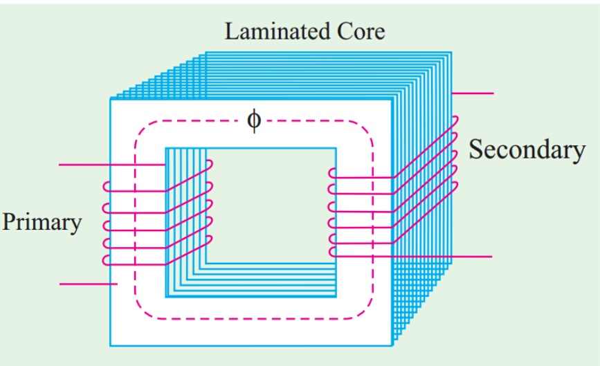
The coils used are form-wound and are of the cylindrical type. The general form of these coils may be circular or oval or rectangular. In small size core-type transformers, a simple rectangular core is used with cylindrical coils which are either circular or rectangular in form. But for large-size core-type transformers, round
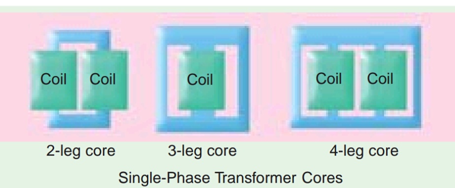
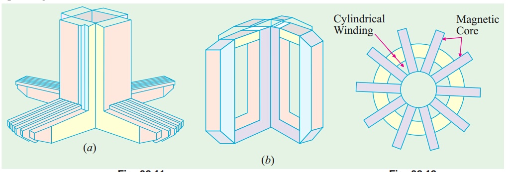
or circular cylindrical coils are used which are so wound as to fit over a cruciform core section as shown in Fig.The circular cylindrical coils are used in most of the core-type transformers because of their mechanical strength. Such cylindrical coils are wound in helical layers with the different layers insulated from each other by paper, cloth, micarta board or cooling ducts. the general arrangement of these coils with respect to the core. Insulating cylinders of fuller board are used to separate the cylindrical windings from the core and from each other. Since the low voltage (LV) winding is easiest to insulate, it is placed nearest to the core

Because of laminations and insulation, the net or effective core area is reduced, due allowance for which has to be made It is found that, in general, the reduction in core sectional area due to the presence of paper, surface oxide etc. is of the order of 10% approximately.
Shell Type Transformer :
In these case also, the coils are form-would but are multi-layer disc type usually wound in the form of pancakes. The different layers of such multi-layer discs are insulated from each other by paper. The complete winding consists of stacked discs with insulation space between the coils–the spaces forming horizontal cooling and insulating ducts. A shell-type transformer may have a simple rectangular form as shown in Fig. or it may have distributed form as shown in fig.

A very commonly-used shell-type transformer is the one known as Berry Transformer–so called after the name of its designer and is cylindrical in form. The transformer core consists of laminations arranged in groups which radiate out from the centre
It may be pointed out that cores and coils of transformers must be provided with rigid mechanical bracing in order to prevent movement and possible insulation damage. Good bracing reduces vibration and the objectionable noise–a humming sound–during operation.
The spiral-core transformer employs the newest development in core construction. The core is assembled of a continuous strip or ribbon of transformer steel wound in the form of a circular or elliptical cylinder. Such construction allows the core flux to follow the grain of the iron. Cold-rolled steel of high silicon content enables the designer to use considerably higher operating flux densities with lower loss per kg. The use of higher flux density reduces the weight per kVA. Hence, the advantages of such construction are
- a relatively more rigid core
- lesser weight and size per kVA rating
- lower iron losses at higher operating flux densities and
- lower cost of manufacture.
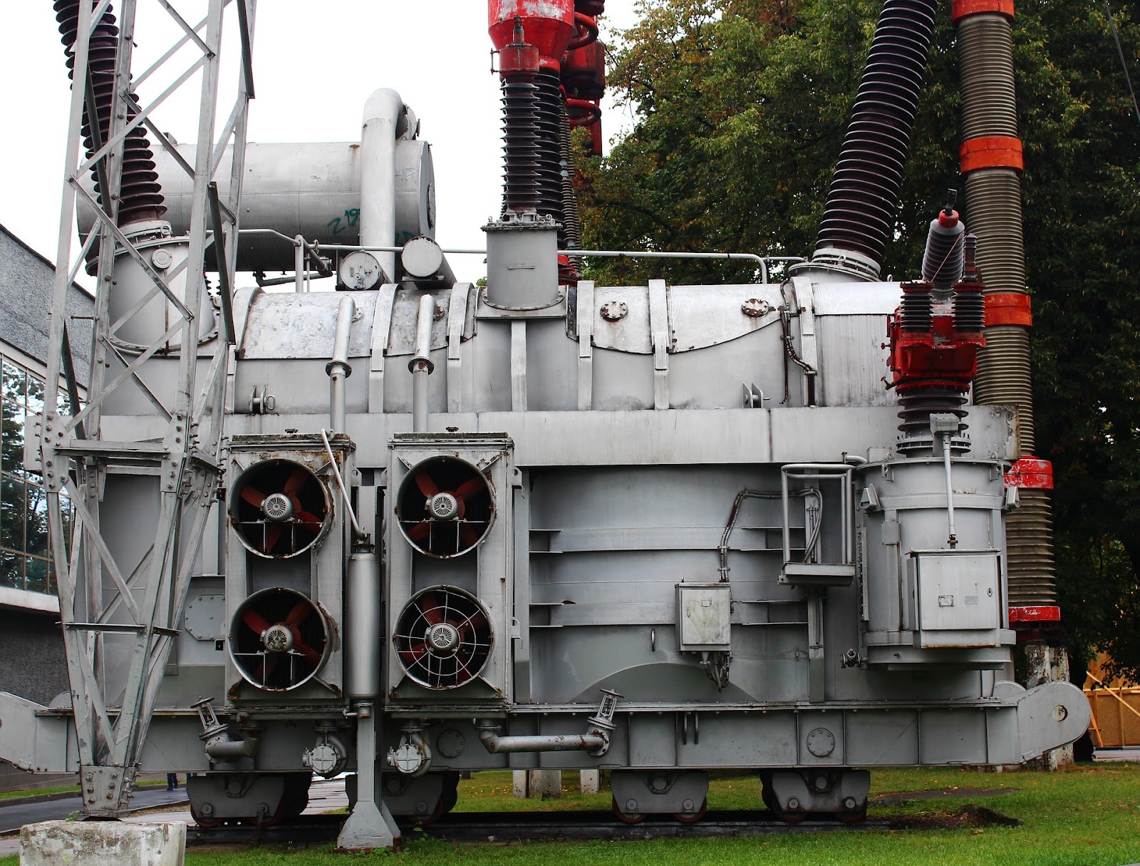
Transformers are generally housed in tightly-fitted sheet-metal ; tanks filled with special insulating oil. This oil has been highly developed and its function is two-fold. By circulation, it not only keeps the coils reasonably cool, but also provides the transformer with additional insulation not obtainable when the transformer is left in the air.
In cases where a smooth tank surface does not provide sufficient cooling area, the sides of the tank are corrugated or provided with radiators mounted on the sides. Good transformer oil should be absolutely free from alkalies, sulphur and particularly from moisture. The presence of even an extremely small percentage of moisture in the oil is highly detrimental from the insulation viewpoint because it lowers the dielectric strength of the oil considerably. The importance of avoiding moisture in the transformer oil is clear from the fact that even an addition of 8 parts of water in 1,000,000 reduces the insulating quality of the oil to a value generally recognized as below standard. Hence, the tanks are sealed airtight in smaller units. In the case of large-sized transformers where complete air-tight construction is impossible, chambers known as breathers are provided to permit the oil inside the tank to expand and contract as its temperature increases or decreases. The atmospheric moisture is entrapped in these breathers and is not allowed to pass on to the oil.
Another thing to avoid in the oil is sledging which is simply the decomposition of oil with long and continued use. Sledging is caused principally by exposure to oxygen during heating and results in the formation of large deposits of dark and heavy matter that eventually clogs the cooling ducts in the transformer. No other feature in the construction of a transformer is given more attention and care than the insulating materials, because the life on the unit almost solely depends on the quality, durability and handling of these materials. All the insulating materials are selected on the basis of their high quality and ability to preserve high quality even after many years of normal use.
All the transformer leads are brought out of their cases through suitable bushings. There are many designs of these, their size and construction depending on the voltage of the leads. For moderate voltages, porcelain bushings are used to insulate the leads as they come out through the tank. In general, they look almost like the insulators used on the transmission lines. In high voltage installations, oil-filled or capacitor type bushings are employed. The choice of core or shell-type construction is usually determined by cost, because similar characteristics can be obtained with both types. For very high-voltage transformers or for multi winding design, shell type construction is preferred by many manufacturers.
In this type, usually the mean length of coil turn is longer than in a comparable core-type design. Both core and shell forms are used and the selection is decided by many factors such as voltage rating, kVA rating, weight, insulation stress, heat distribution etc. Another means of classifying the transformers is according to the type of cooling employed. The following types are in common use :
(a) oil-filled self-cooled
(b) oil-filled water-cooled
(c) air-blast type
Small and medium size distribution transformers–so called because of their use on distribution systems as distinguished from line transmission–are of type (a). The assembled windings and cores of such transformers are mounted in a welded, oil-tight steel tank provided with steel cover. After putting the core at its proper place, the tank is filled with purified, high quality insulating oil. The oil serves to convey the heat from the core and the windings to the case from where it is radiated out to the surroundings.
For small size, the tanks are usually smooth-surfaced, but for larger sizes, the cases are frequently corrugated or fluted to get greater heat radiation area without increasing the cubical capacity of the tank. Still larger sizes are provided with radiators or pipes. Construction of very large self-cooled transformers is expensive, a more economical form of construction for such large transformers is provided in the oil-immersed, water-cooled type. As before, the windings and the core are immersed in the oil, but there is mounted near the surface of oil, a cooling coil through which cold water is kept circulating. The heat is carried away by this water. The largest transformers such as those used with high-voltage transmission lines, are constructed in this manner. Oil-filled transformers are built for outdoor duty and as these require no housing other than their own, a great saving is thereby effected. These transformers require only periodic inspection. For voltages below 25,000 V, transformers can be built for cooling by means of an air-blast. The transformer is not immersed in oil, but is housed in a thin sheet-metal box open at both ends through which air is blown from the bottom to the top by means of a fan or blower.
Please Comment Below If You Have Any Doubts and Suggestions..